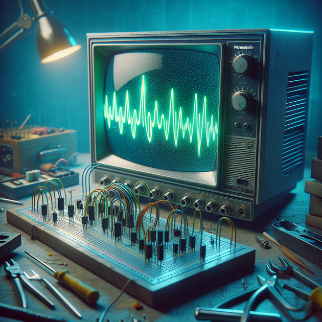
Converting a classic television into a working oscilloscope is a popular DIY project—but running into crt tv oscilloscope troubleshooting challenges is common. If you’re not seeing the expected waveform or any output at all after connecting your audio signal to the horizontal coil via a 1/4” jack, you’re not alone.
Understanding the Basics of CRT Oscilloscopes
A cathode ray tube (CRT) television works by steering an electron beam across the screen with magnetic coils—one for horizontal movement and one for vertical. In a homemade oscilloscope setup:
- The vertical coil usually receives the test signal (like audio from your preamp).
- The horizontal coil often stays connected to its original circuit to keep the trace moving.
- Direct connection of audio signals to these coils is risky without protection.
Most common issues happen because the circuit inside the TV expects specific signals—not the line-level output from an amplifier or preamp.
Key Problems in CRT TV Oscilloscope Troubleshooting
If you’re getting no response after connecting your line-level signal to the horizontal coil through a 1/4” jack, consider these typical trouble areas:
- Signal Level Mismatch: Audio amplifiers output much lower voltage than what’s needed to deflect a heavy coil.
- Circuit Protection: Without resistors or capacitors in place, you could damage both your amp and the television.
- TV Circuit Interference: The existing horizontal sweep circuit may override or block external signals.
- Grounding Issues: A floating ground can prevent current flow or cause dangerous shorts.
A good overview of how TVs process video and sync signals can be found at Electronics Tutorials. This helps make sense of what’s happening inside the set.
Should You Build an Interface Circuit?
Most successful DIYers use a simple interface circuit between their signal source and the deflection coils. Why? Because:
- The coils require higher voltage/current than most audio outputs provide.
- An interface isolates sensitive equipment (like your amp) from high voltages in the TV.
- You can add controls like gain adjustment or DC blocking capacitors for safety.
A basic buffer amplifier or even an op-amp circuit can boost your signal safely. For ideas on circuit design basics, check out resources like All About Circuits. Even something as simple as an audio transformer can help.
Anecdote: When Bigger Isn’t Better
One reader shared their story about lugging a massive Panasonic 32-inch CRT across their workshop—only to realize that direct wiring gave no result and nearly fried their amp. After building a quick transistor-based amplifier circuit and adding fuses for protection, they finally saw that telltale squiggle on screen without risking personal injury or equipment damage.
Troubleshooting Checklist for DIY CRT Oscilloscopes
Here’s a handy list if you’re stuck:
- Confirm which coil (vertical/horizontal) you’re using—most use vertical for signal input.
- Add an interface/buffer circuit between audio source and deflection coil.
- Double-check all grounds are securely tied together (amp + TV chassis).
- Never connect directly without DC blocking capacitors and current-limiting resistors.
- If nothing appears on screen, reconnect original wiring briefly to check if TV still works normally.
For more electrical safety advice when working on high-voltage gear like old TVs, see this guide from Hackaday. Always unplug before poking around!
Final Thoughts
Turning an old television into an oscilloscope is rewarding but rarely plug-and-play. Most issues come down to mismatched voltages or lack of isolation between devices. With careful planning—and perhaps building a small interface circuit—you’ll improve both results and safety.
Ever tried this conversion yourself? What unexpected roadblocks did you hit—and how did you solve them?

Leave a Reply